Co-Creative Robots in Architecture
UR10e painting and rod bending, Detmolder Räume 2026

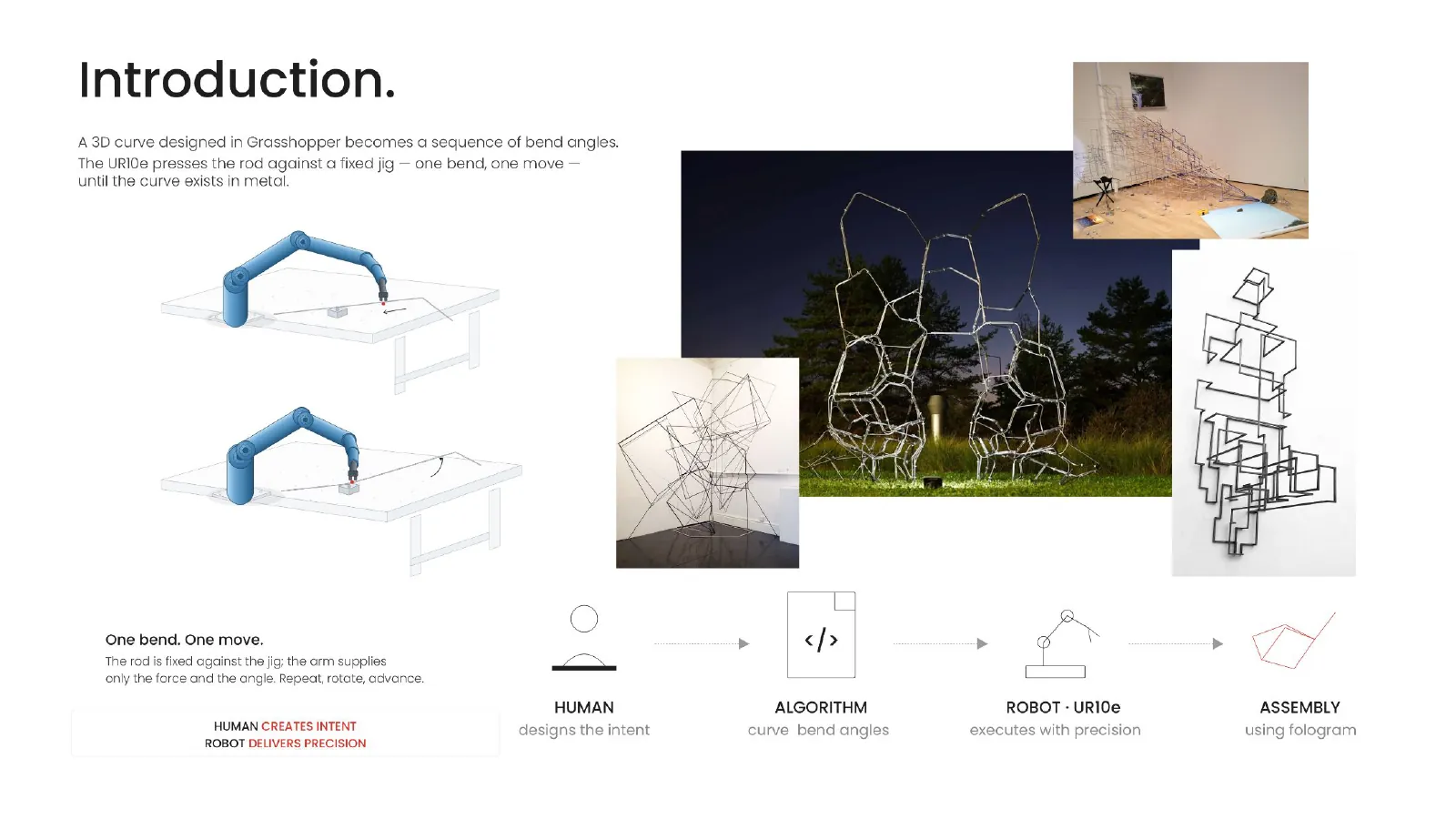
Co-Creative Robots in Architecture was a seminar week at the Detmold School of Design, TH OWL, run during Detmolder Räume under Victor Sardenberg. I assisted him in conducting it, and the students through it. The question behind it was not whether a robot can build something, but what it is like to design with one: a UR10e collaborative arm as a partner in the loop, driven from Grasshopper, with the geometry, the tool and the robot program all developed together.
The week ran as two exercises. The first put a brush in the robot's hand and used painting to learn the whole chain — define the robot, build target planes, choose movement types, simulate, then send the program to the real arm. The second was the real piece: bending metal rods into modules and aggregating them into a suspended space frame, which meant designing the rod geometry, the gripper, the bending jig and the hanging details as one system.
Everything below comes from the presentation we gave at the end of the week; the full deck is at the bottom of this page.
- Type
- Workshop — seminar week
- Role
- Assistant — supporting Victor Sardenberg in running the week, and the students through it
- When
- May 2026, Detmolder Räume week
- Module
- MID2050 — MID / MIAD seminar
- Supervision
- Victor Sardenberg, Ph.D.
- Where
- Detmold School of Design, TH OWL
- Robot
- Universal Robots UR10e
- Material
- Metal rods, string, printed hooks
- Rhinocerosgeometry and the aggregation
- Grasshoppertarget planes, tool definition, the program
- Remote URupload and run on the arm
Part 1 — Painting
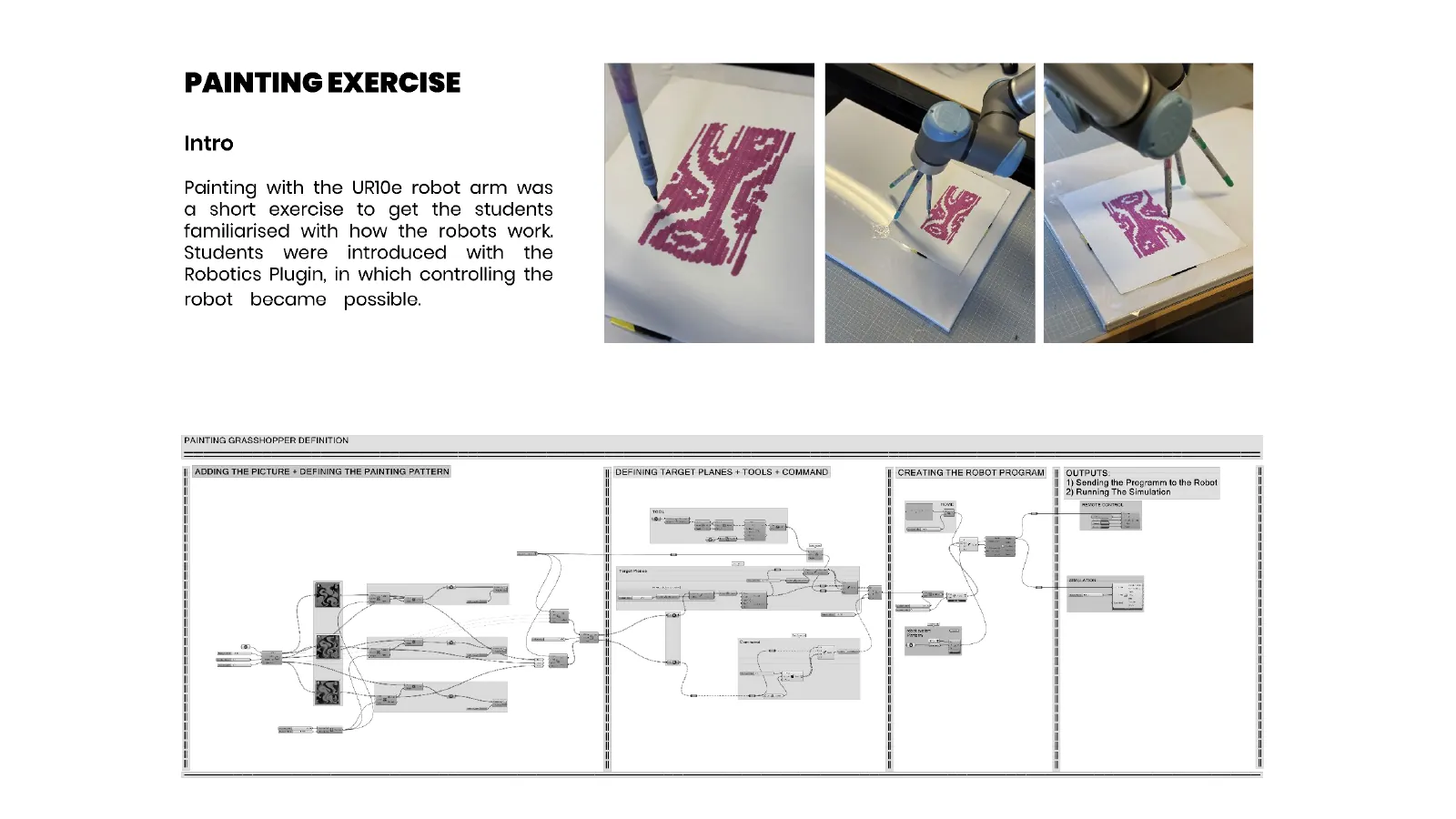
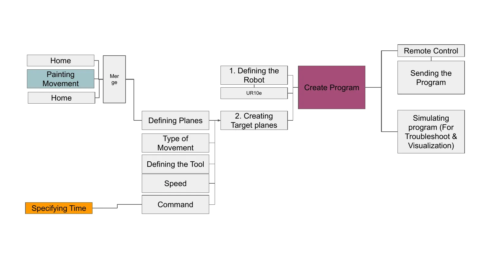
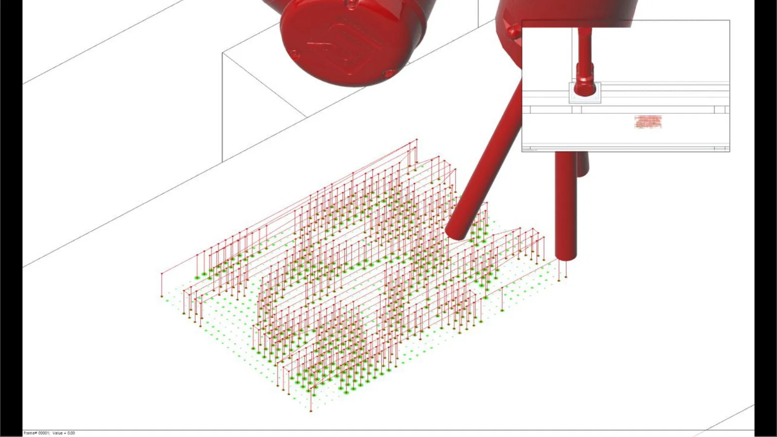
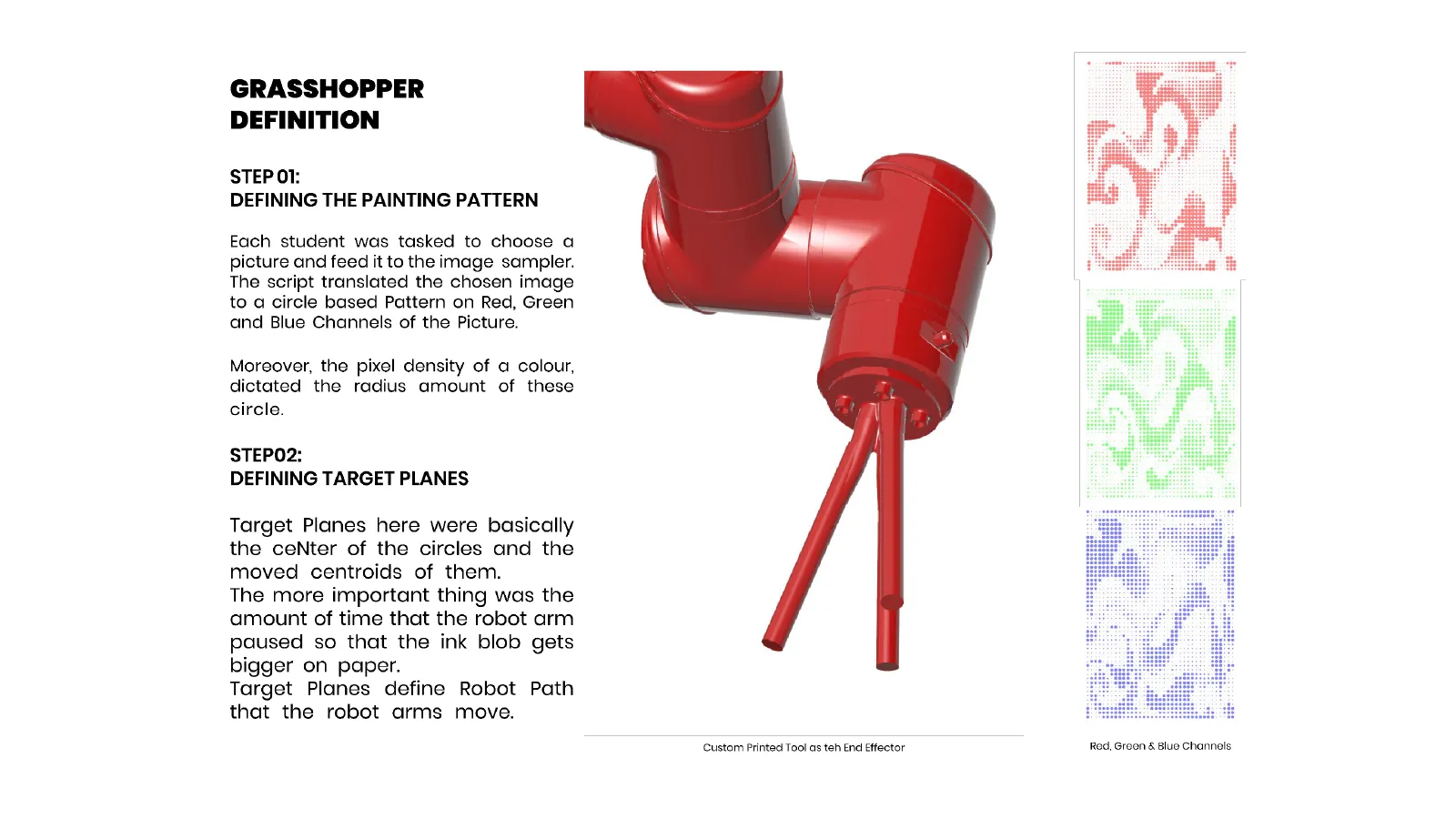
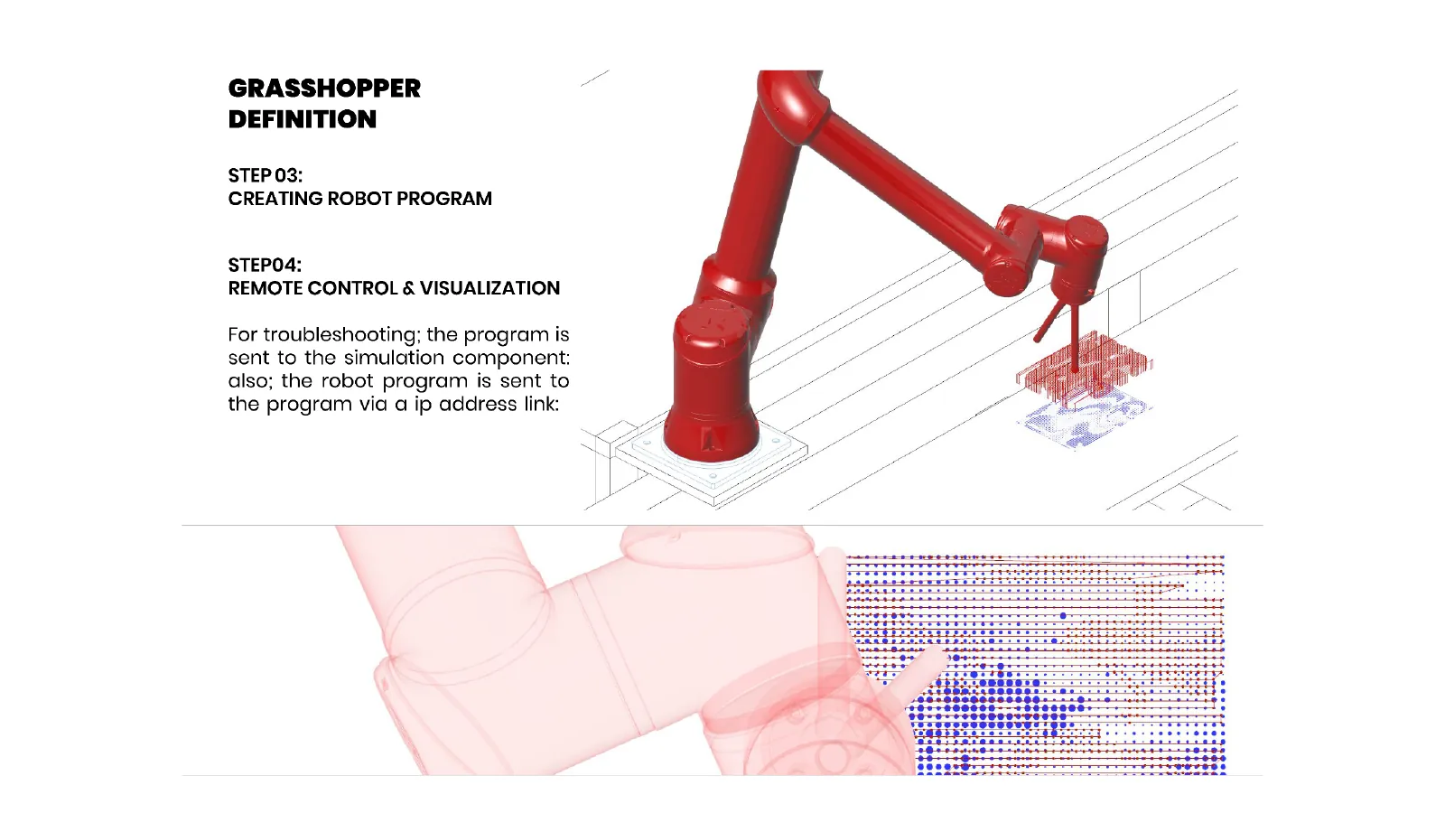
The painting exercise existed to make the whole pipeline visible in a single afternoon. A brush is a forgiving tool: if a plane is a few millimetres out, you get a wobbly line rather than a crash. So the first program did everything the second one would have to do — load the robot, define target planes from a curve, pick a movement type, define the tool and its speed, merge the commands into a program, simulate it for reachability and collisions, and only then send it over.
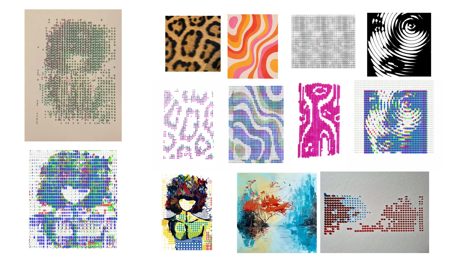
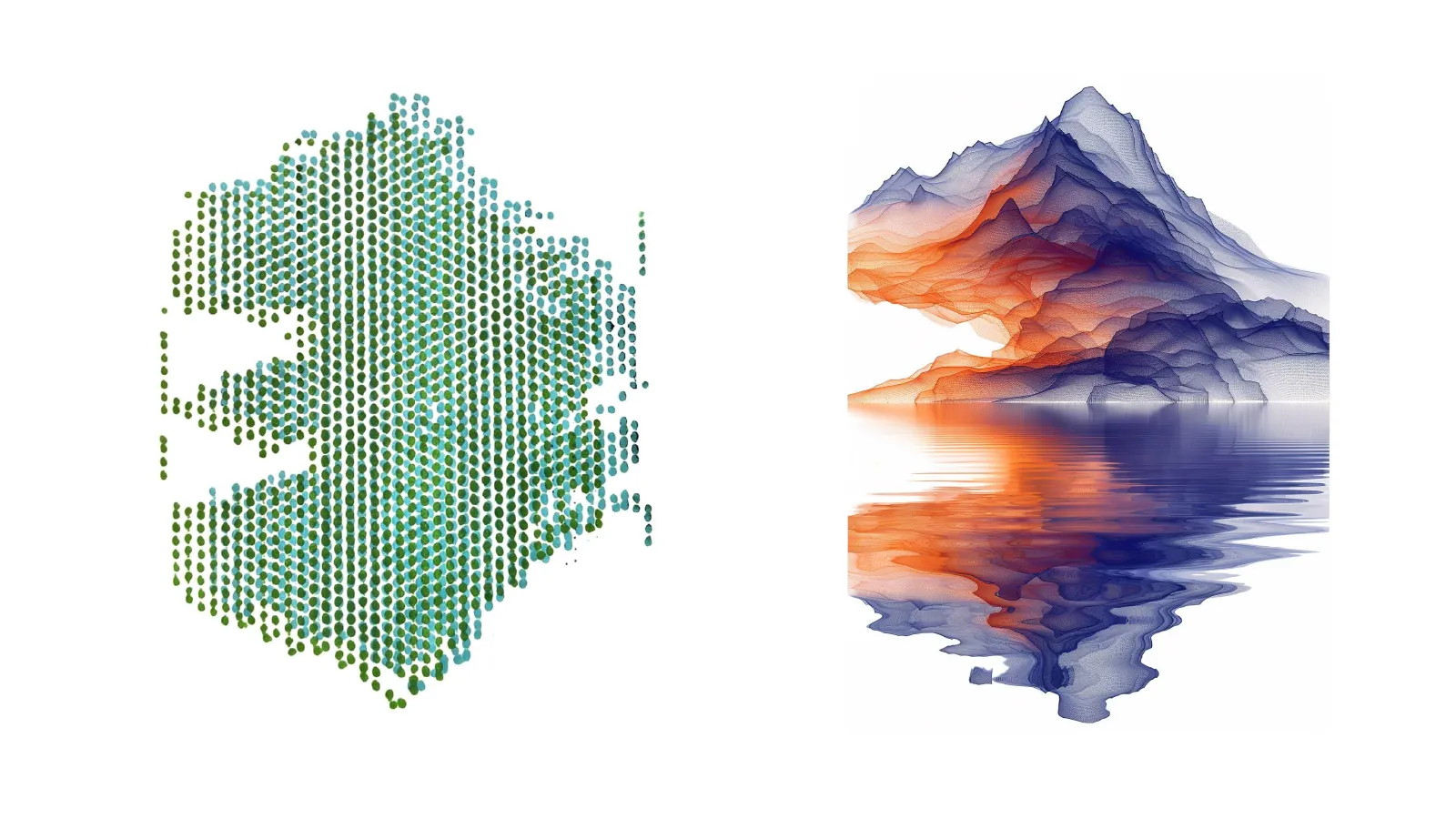
What came back was a set of paintings the robot made from patterns we generated, and a working mental model of what the arm is actually reading when it moves.
The program, in order
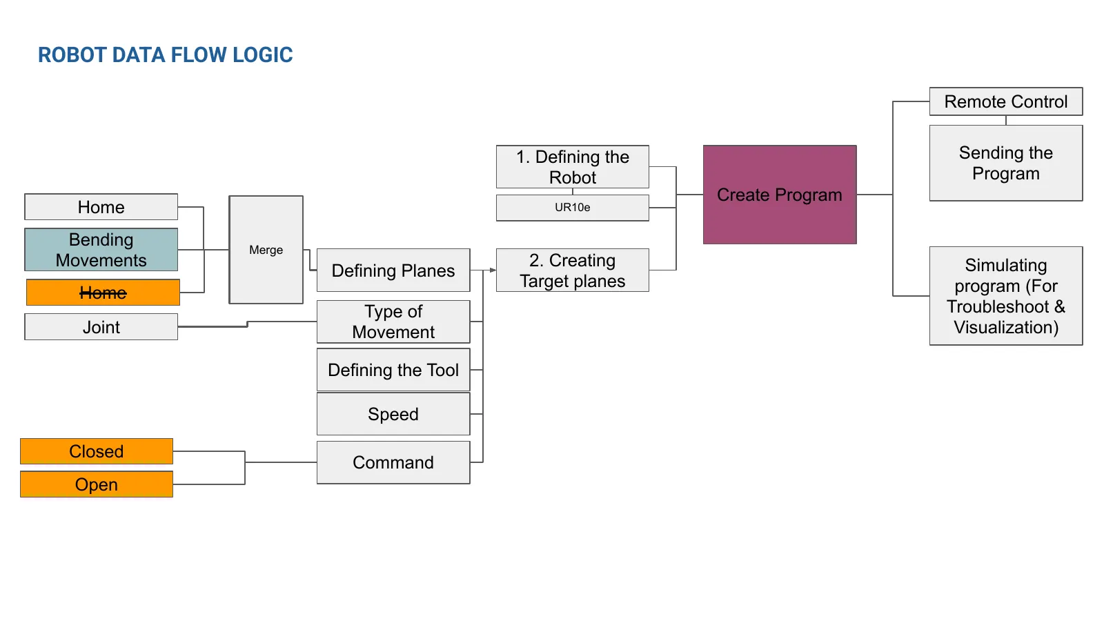
- Define the robot — UR10e
- Create target planes
- Movement type
- Define the tool
- Speed
- Commands
- Merge
- Simulate
- Remote control — send
Part 2 — Design: an aggregation of bent rods
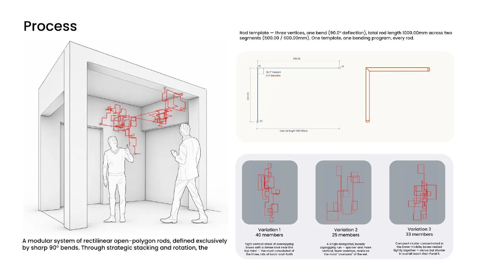
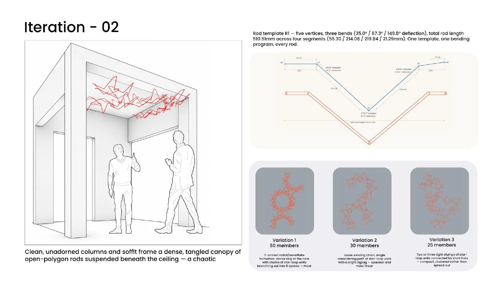
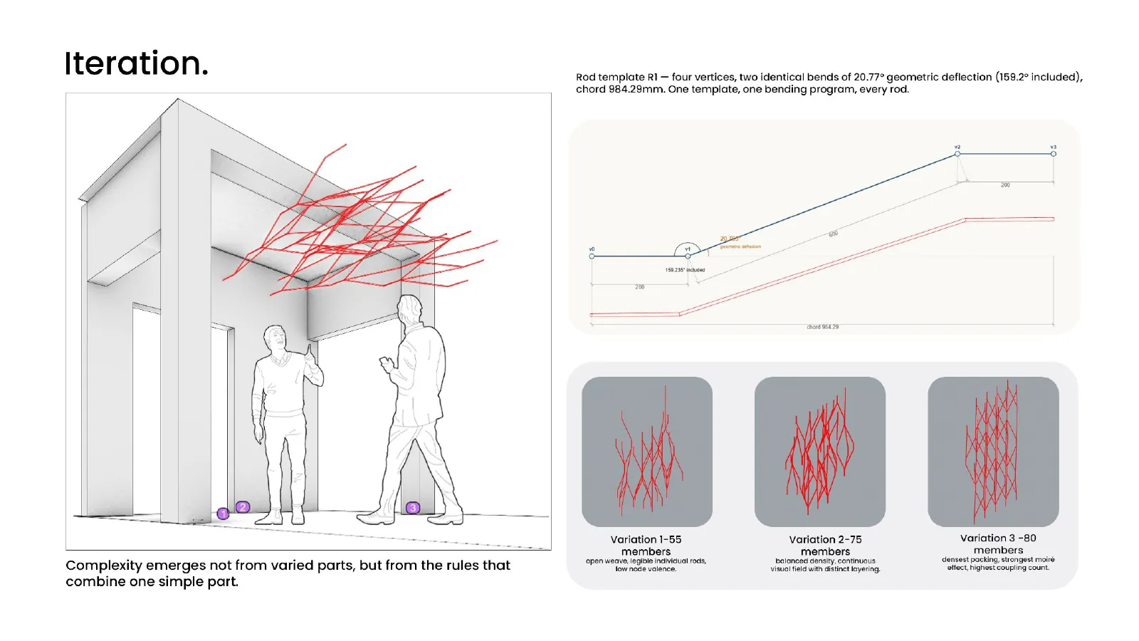
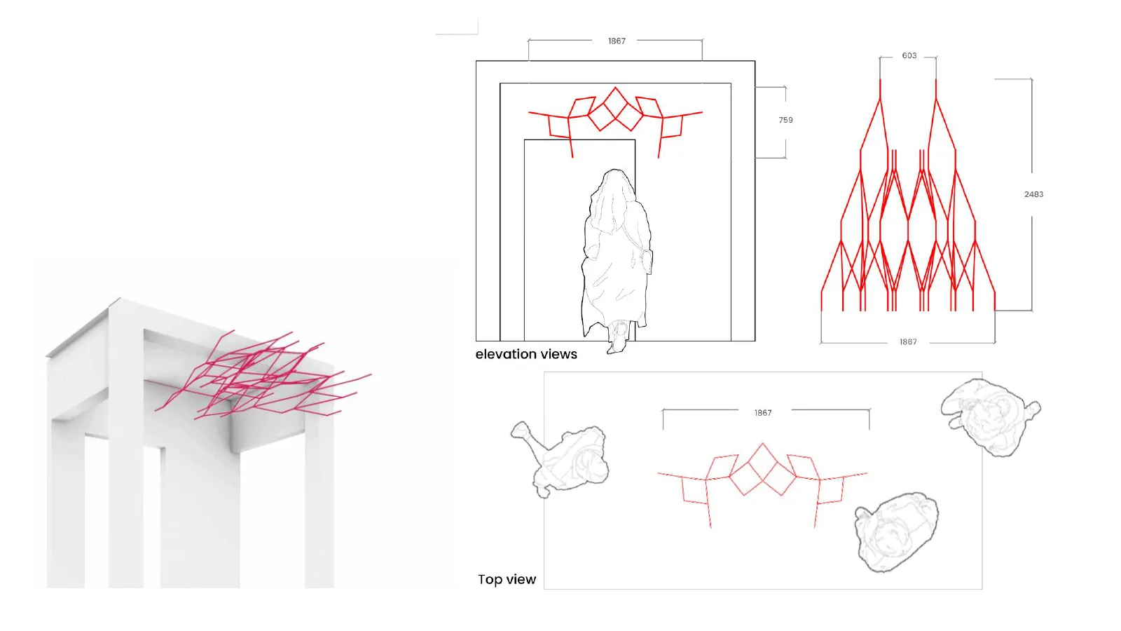
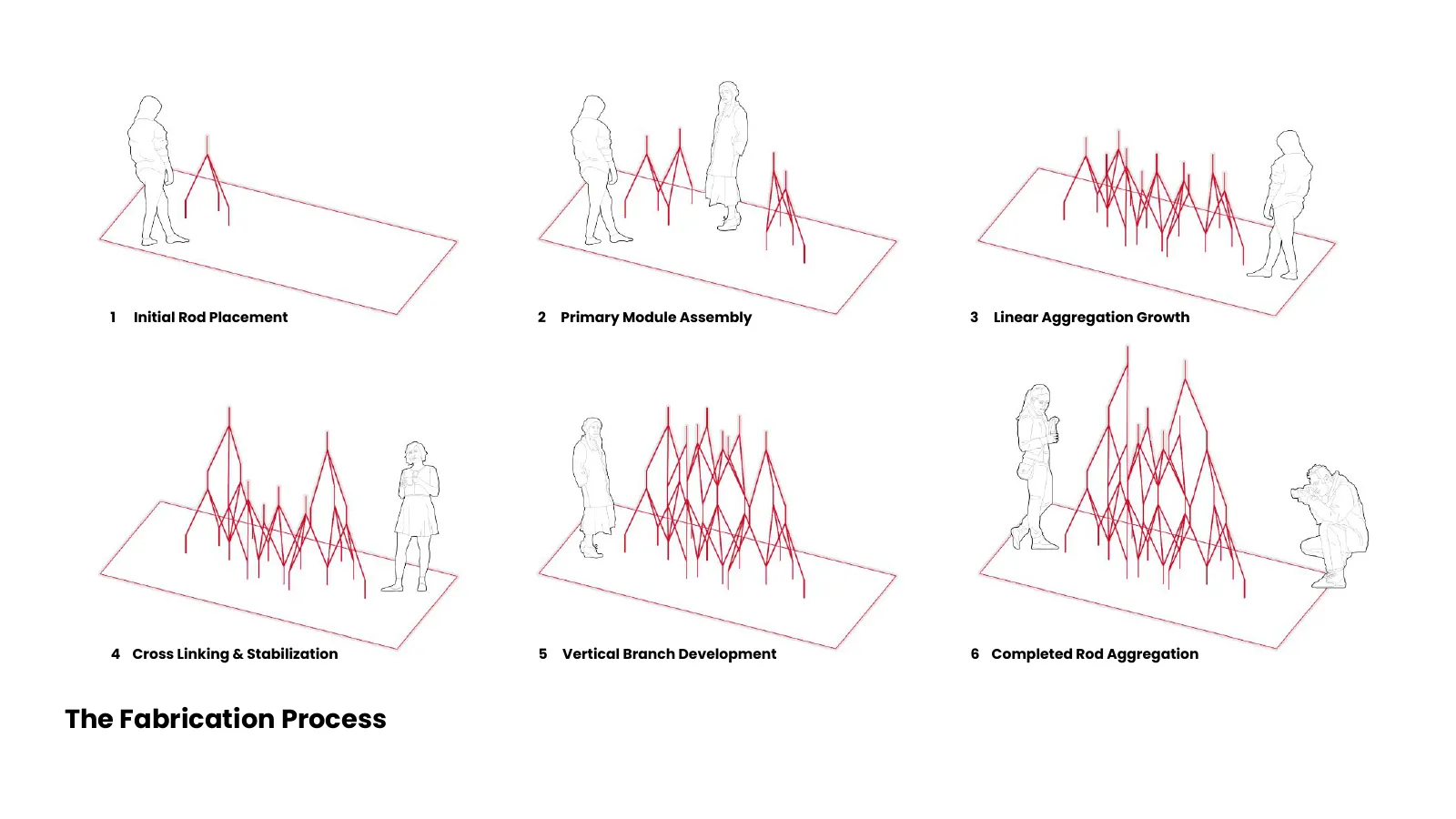
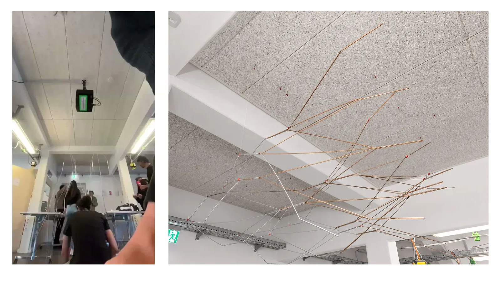
The second exercise had to produce something that stands — or in this case, hangs. We worked with straight metal rods bent by the robot into a repeating module, then aggregated: modules linked end to end, cross-linked for stability, branching vertically, until the whole thing reads as one canopy rather than a pile of parts.
The design iterations were about density and reach: how far the aggregation could grow before it needed another anchor, and how the bends had to change to keep the structure from collapsing into a flat mat.
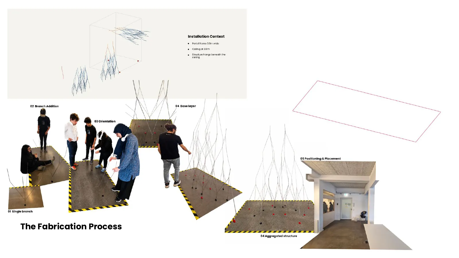
The fabrication process
- 1 Initial rod placement
- 2 Primary module assembly
- 3 Linear aggregation growth
- 4 Cross linking and stabilisation
- 5 Vertical branch development
- 6 Completed rod aggregation
Part 2 — Tools
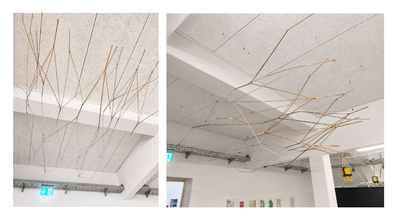
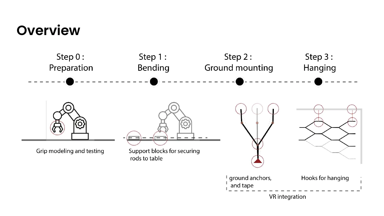
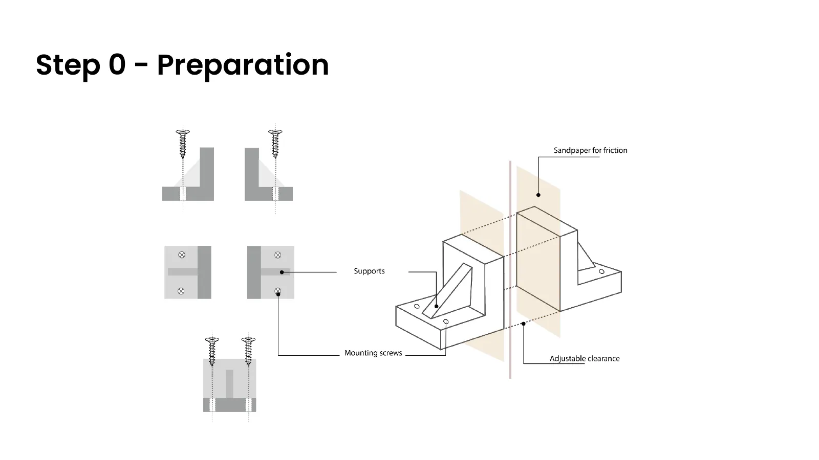
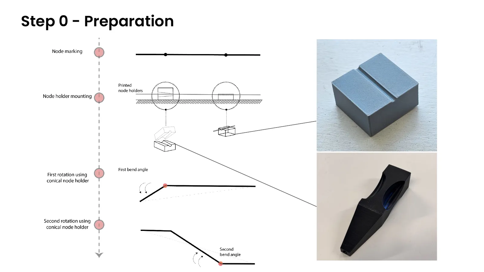
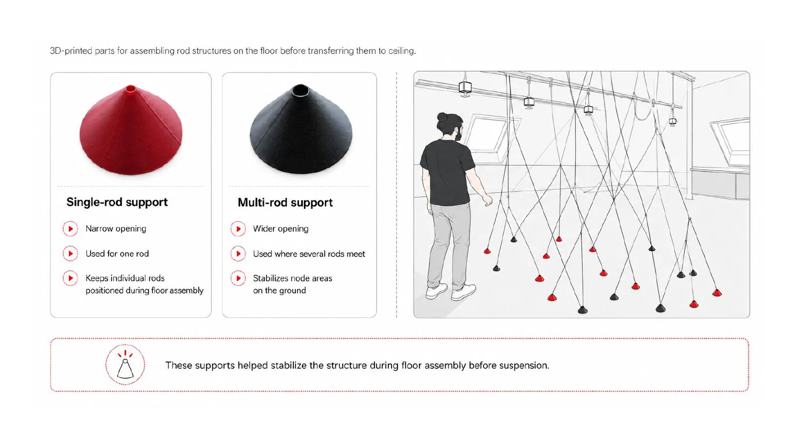
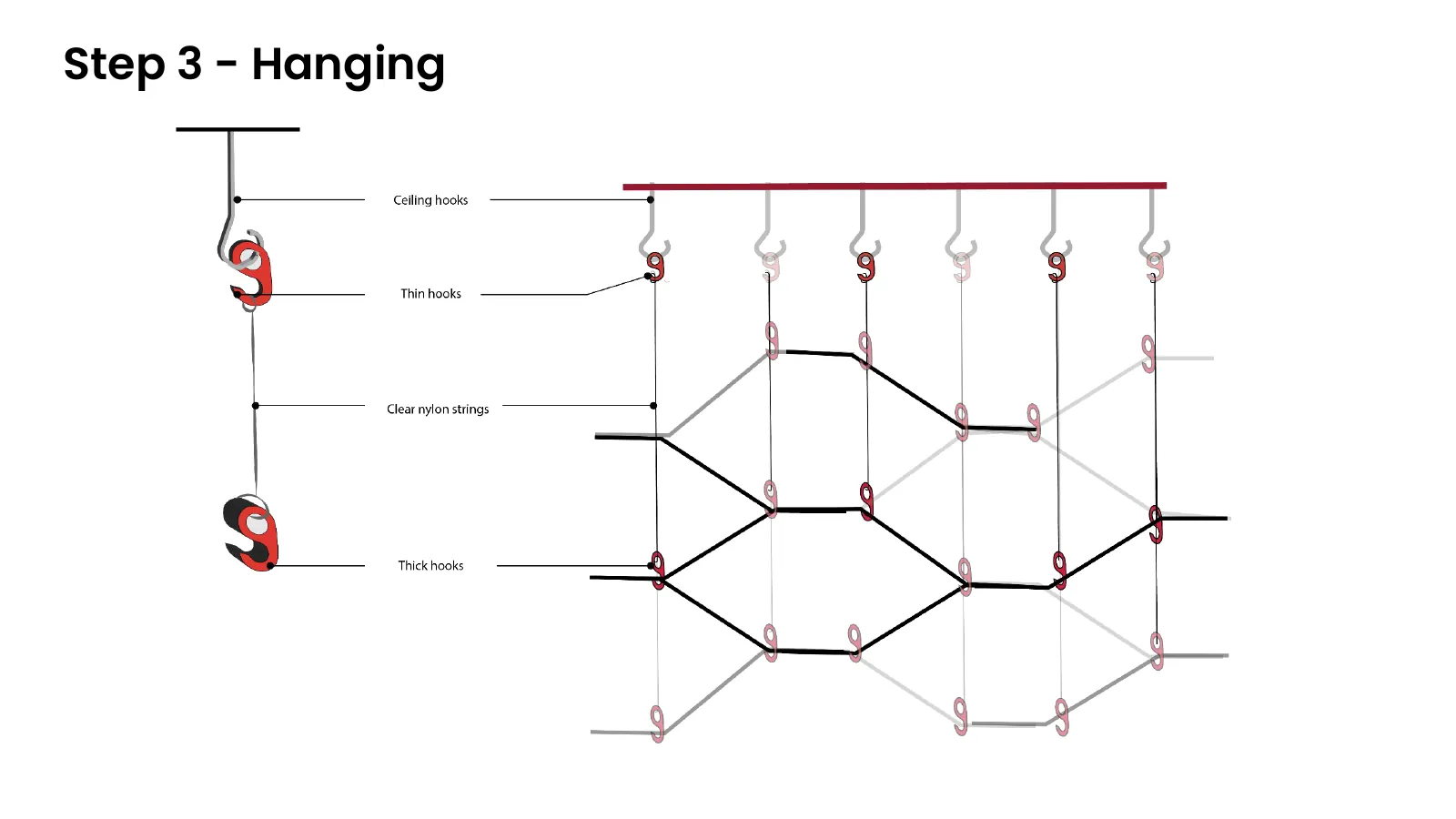
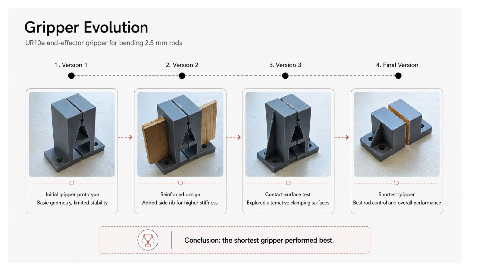
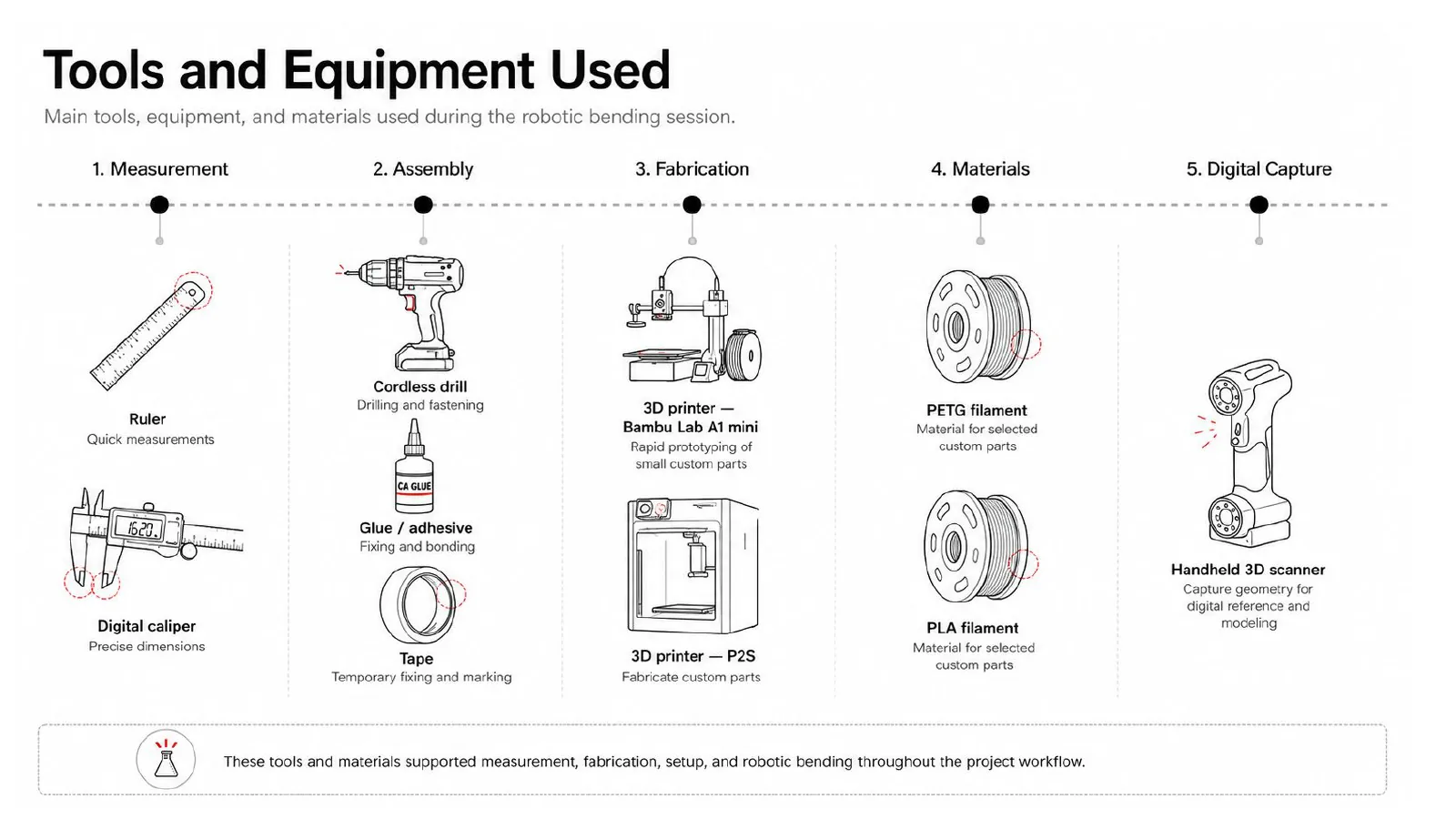
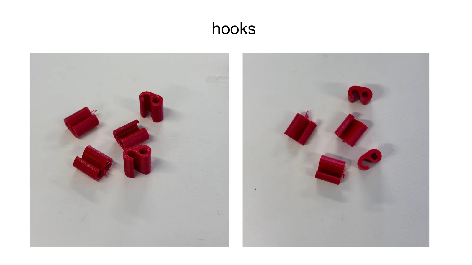
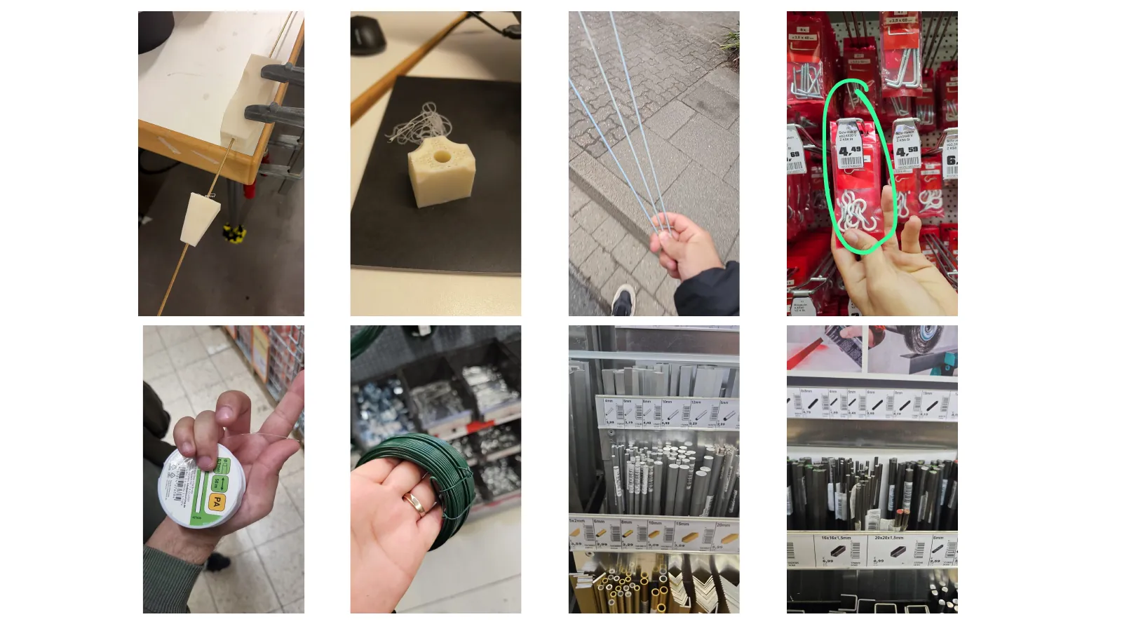
None of this works without the things around the robot. The gripper went through four versions before it could hold a rod hard enough to bend it without crushing or dropping it, and the bending jig had to resist the same force in the opposite direction. Then there was the part nobody designs at the start: how a structure made of springy rods gets off the table and onto the ceiling, which became a set of printed hooks and a hanging sequence of its own.
Four stages
- Step 0 — Preparation
- Step 1 — Bending
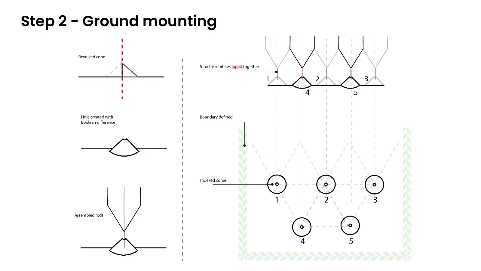
- Step 2 — Ground mounting
- Step 3 — Hanging
Part 3 — The algorithm
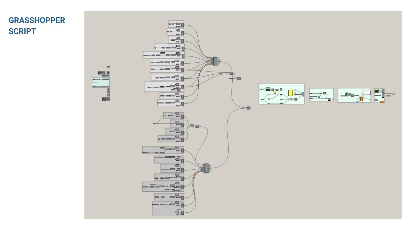
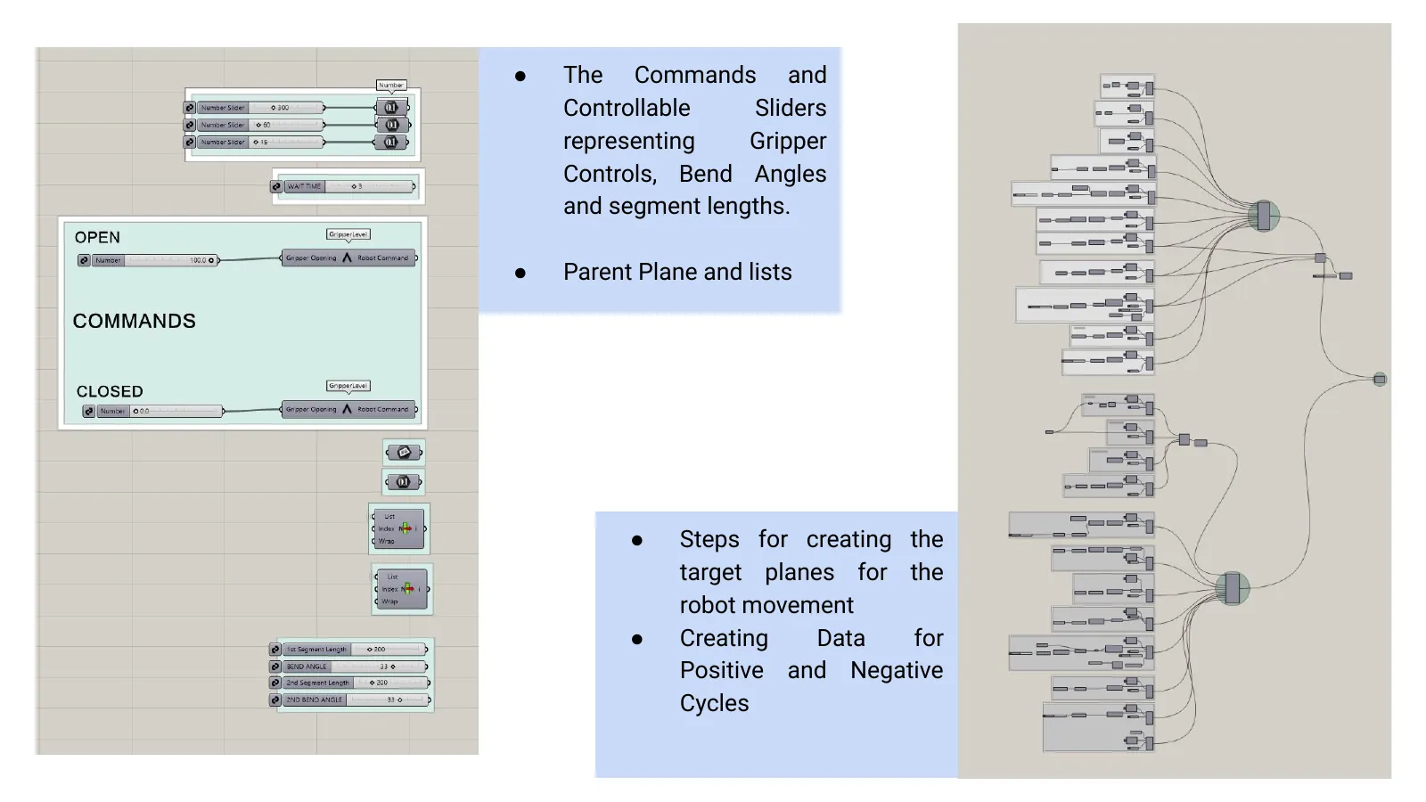
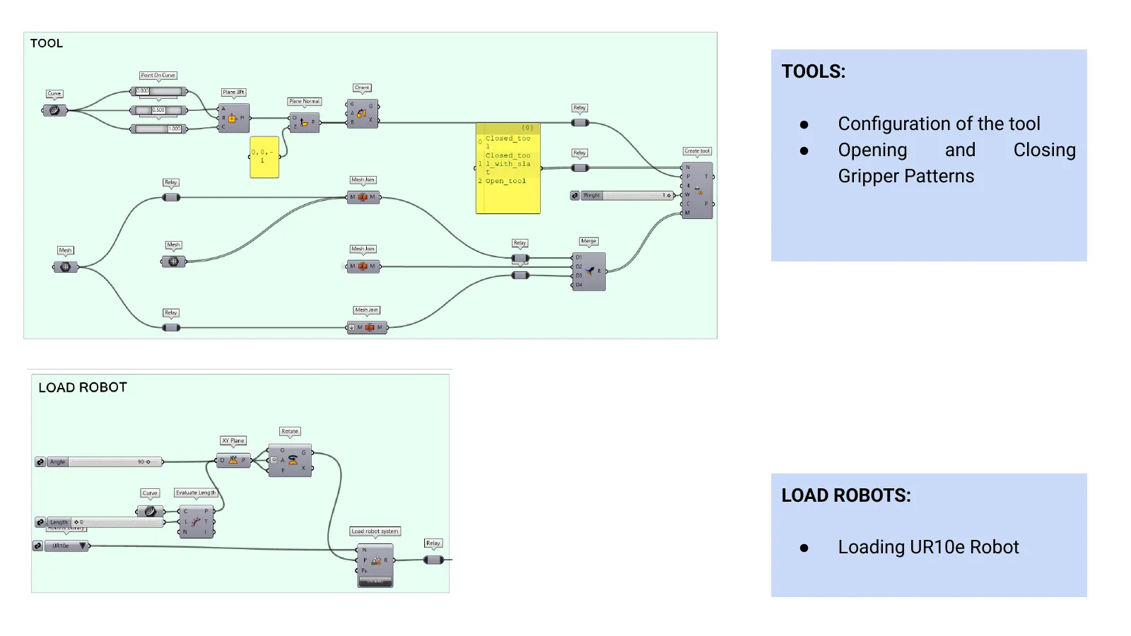
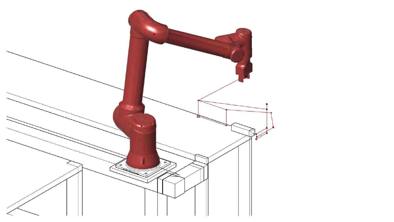
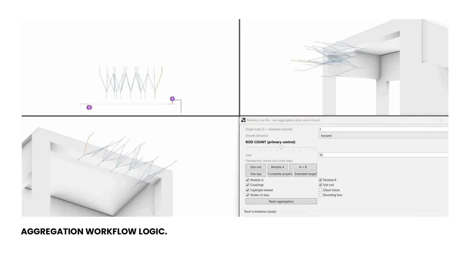
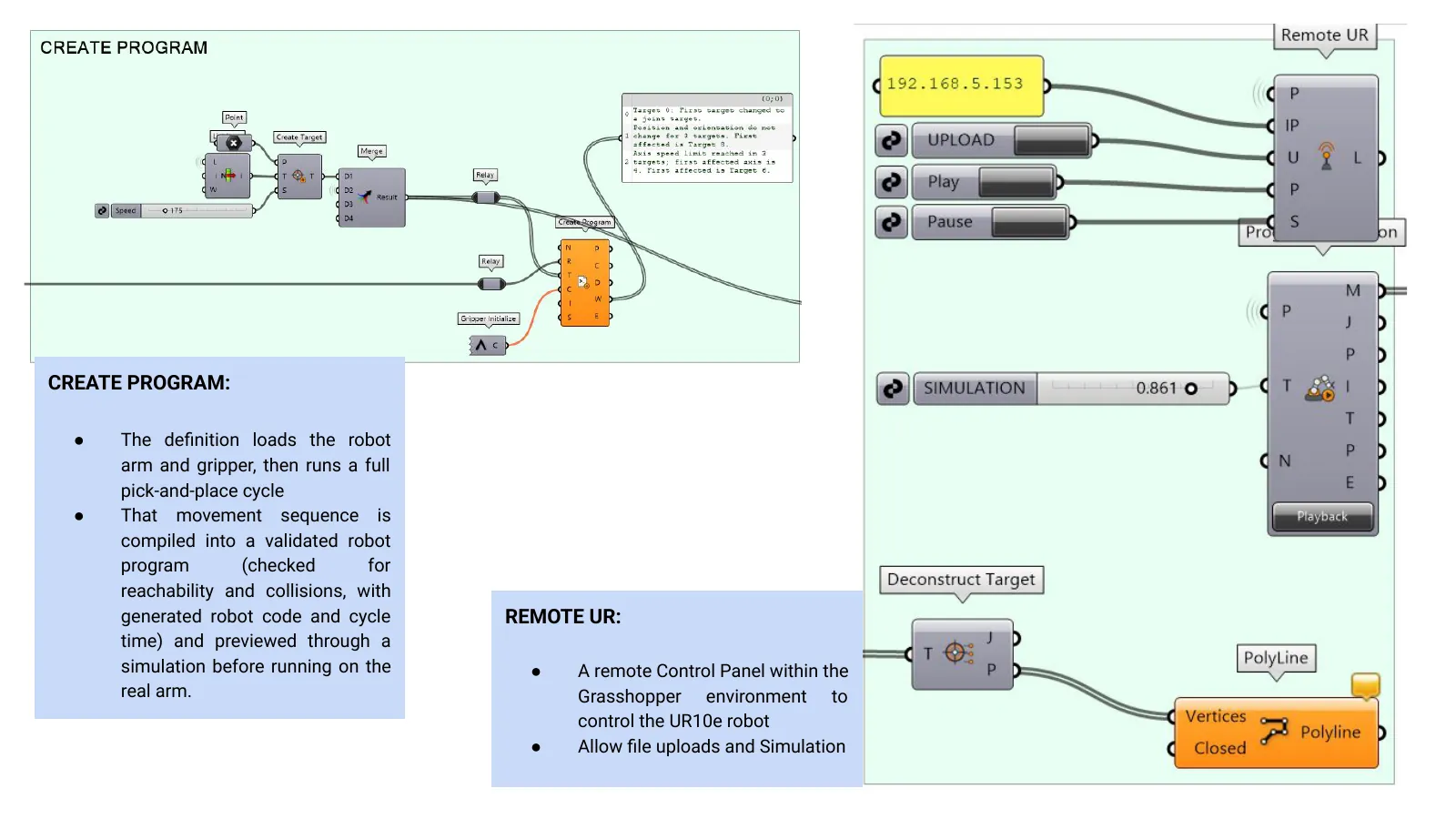
The Grasshopper definition loads the arm and the gripper, builds the target planes for one full pick-place-bend cycle, compiles that sequence into a validated robot program — checked for reachability and collisions, with the robot code and cycle time generated — and previews it in simulation before anything runs. A remote control panel inside Grasshopper then uploads the file and drives the real UR10e.
The commands and sliders expose what actually varies: gripper open and close, bend angles, and the segment lengths between bends. Everything else is derived.
In the definition
- Parent plane and lists
- Target planes
- Positive and negative cycles
- Tool configuration
- Gripper open / close patterns
- Load robot — UR10e
- Create program
- Remote UR panel
One bending cycle, step by step
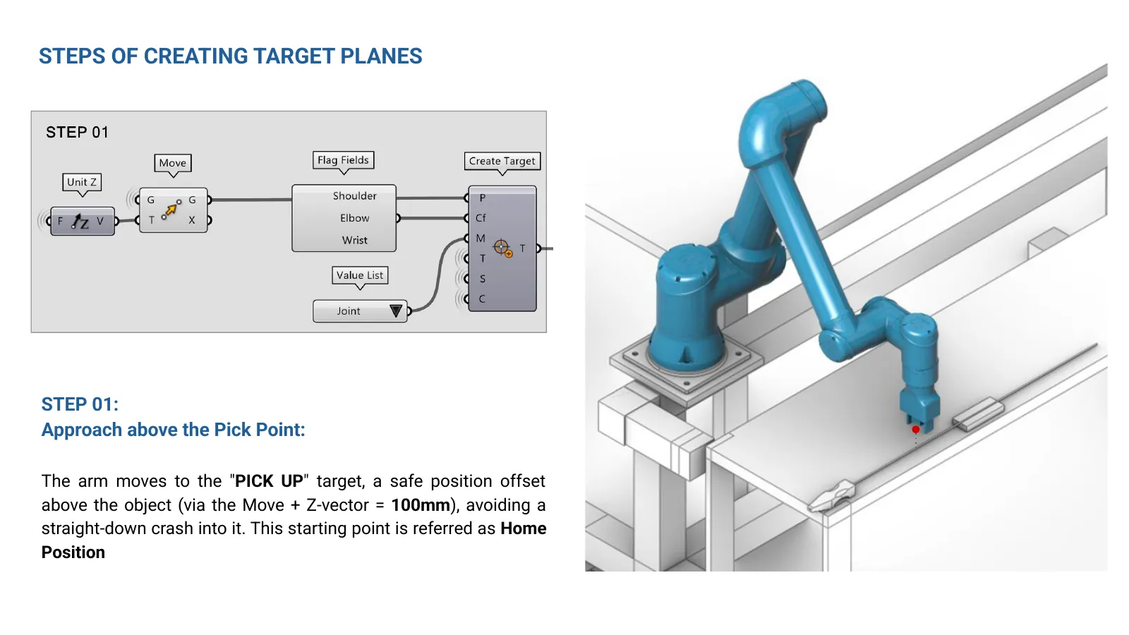
- 01 — Approach above the pick point
The arm moves to the PICK UP target, a safe position offset 100 mm above the rod along the Z vector, rather than driving straight down into it. This is the home position every cycle returns to. - 02 — Descent to the pick point
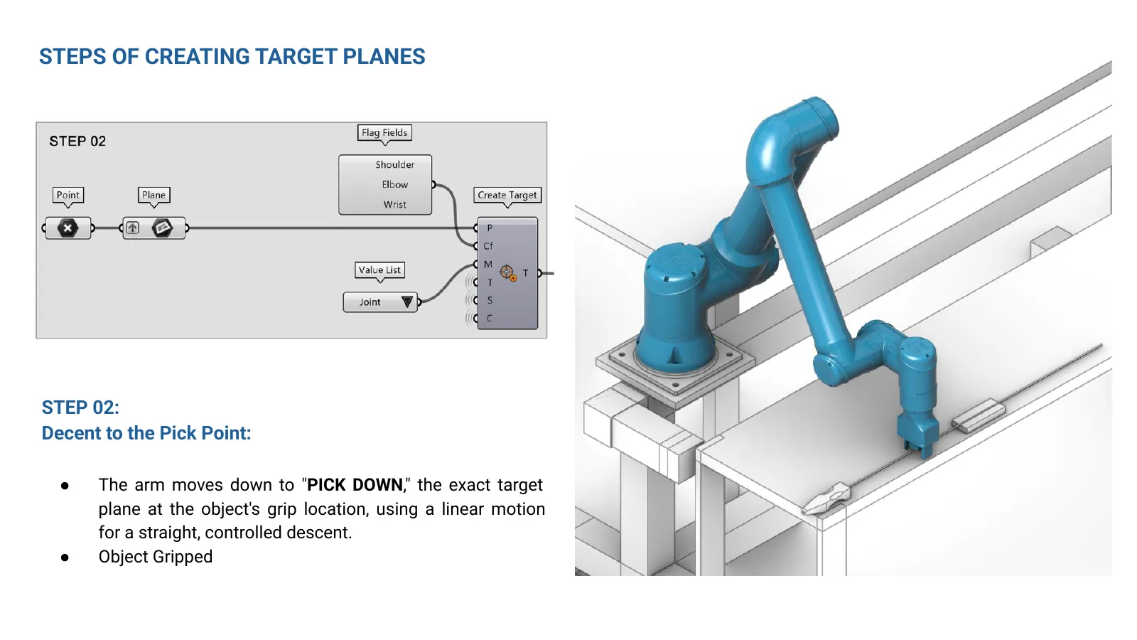
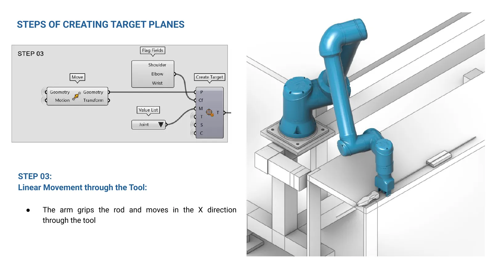
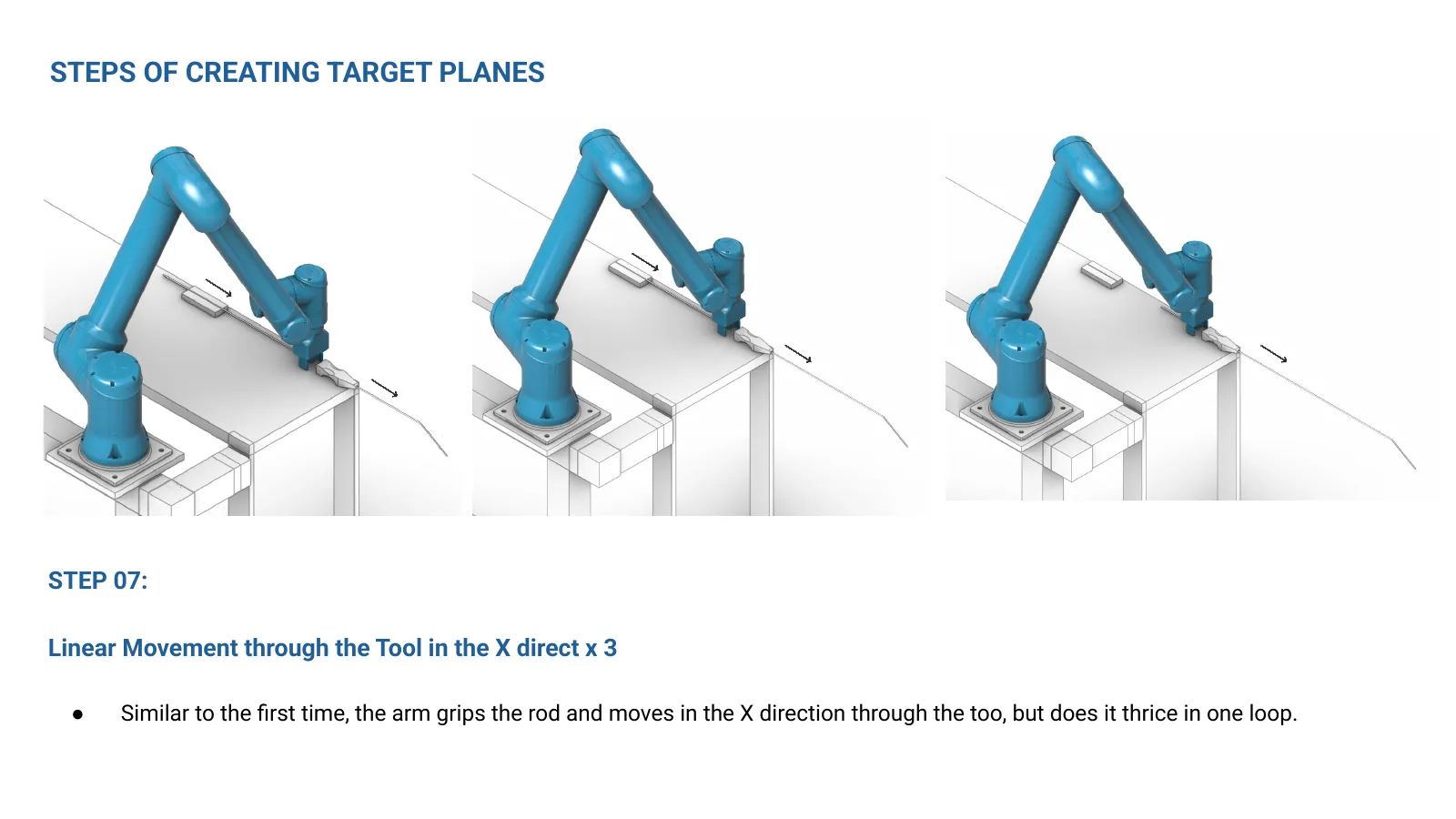
It moves down to PICK DOWN, the exact target plane at the rod's grip location, on a linear motion for a straight, controlled descent. The rod is gripped. - 03 — Linear move through the tool
Holding the rod, the arm moves in X, feeding the rod through the bending tool. - 04 — Move and rotate into the bending position
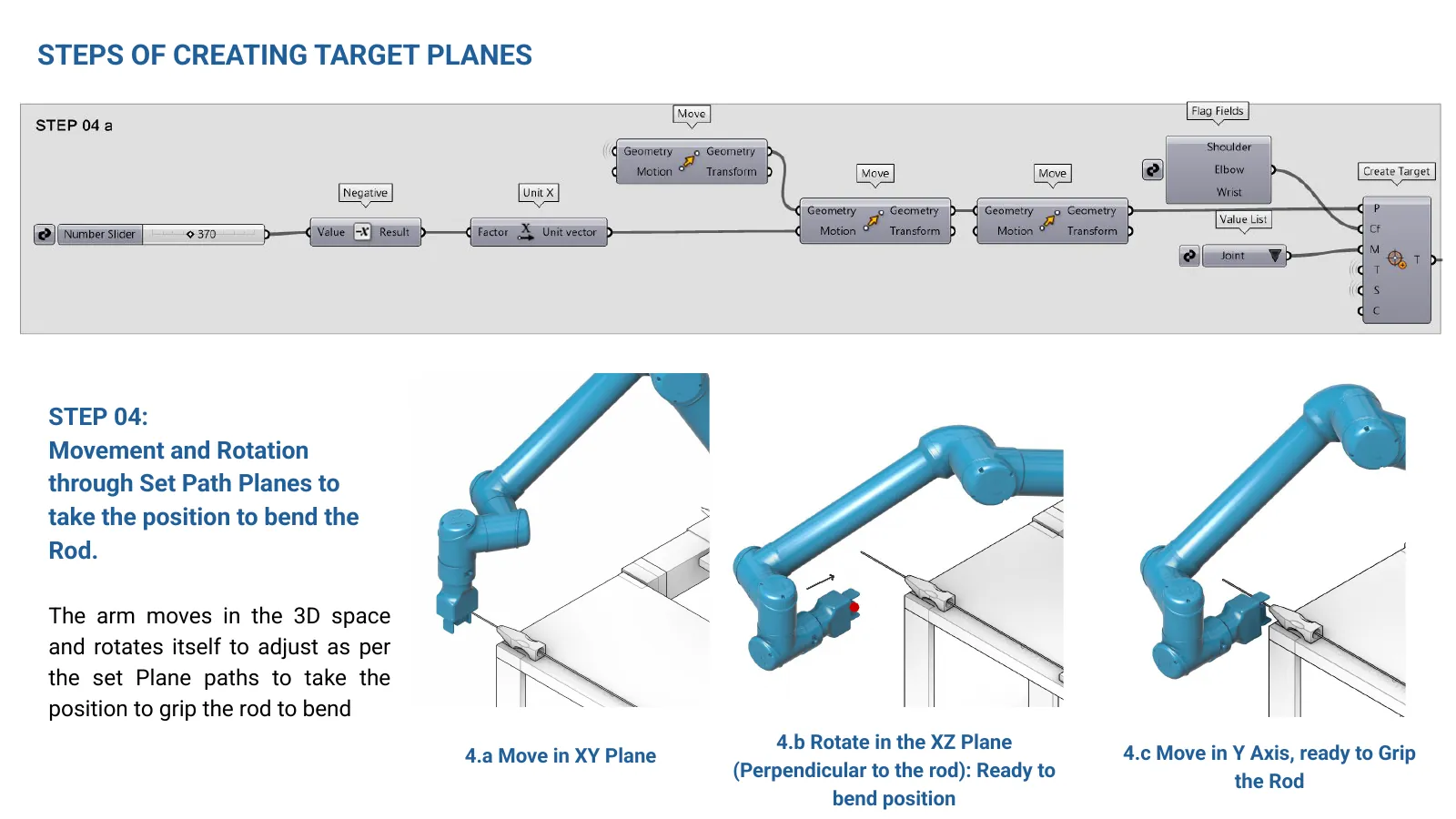
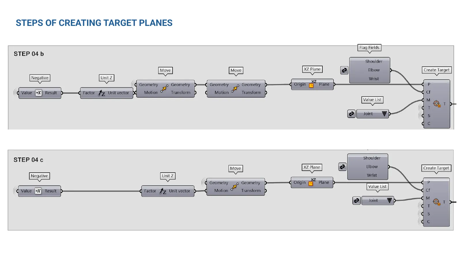
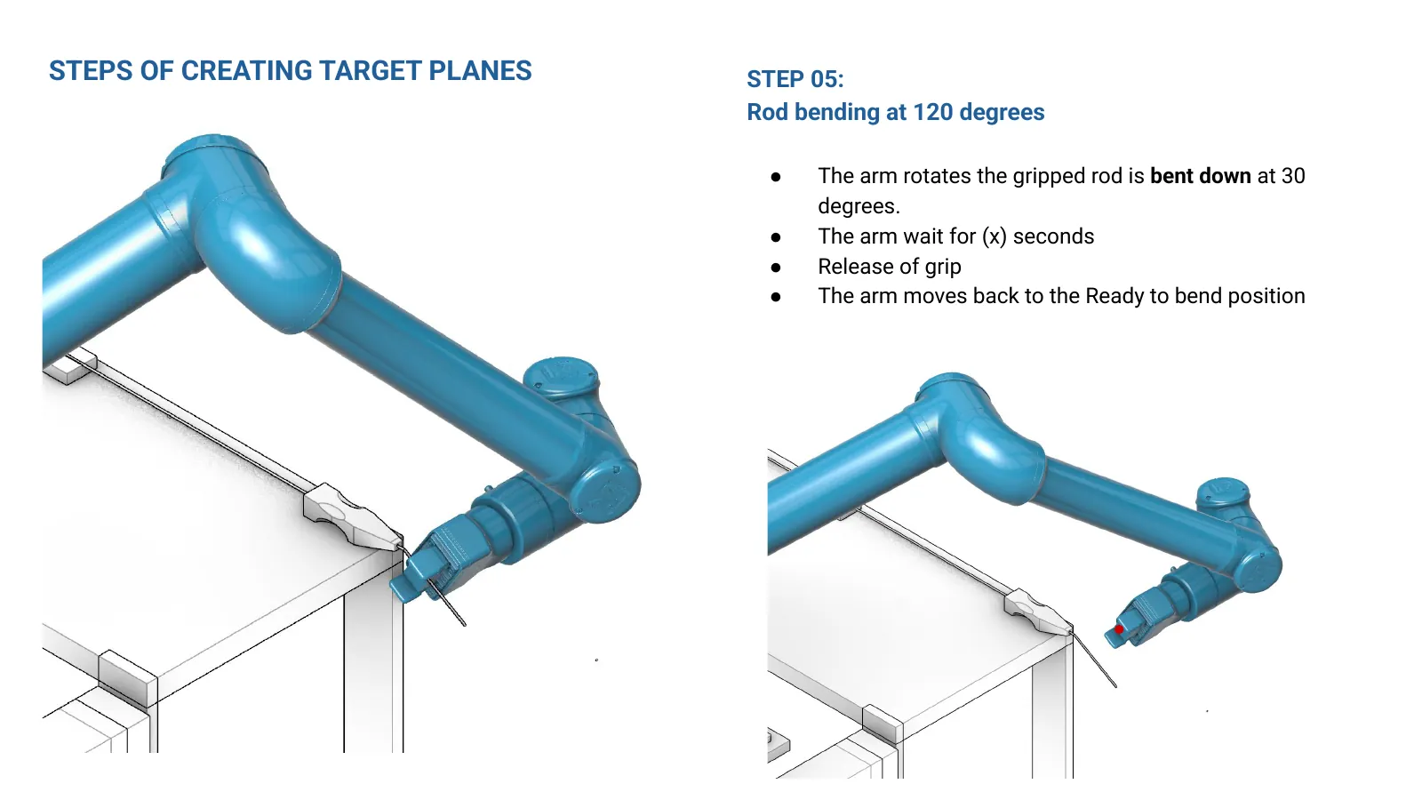
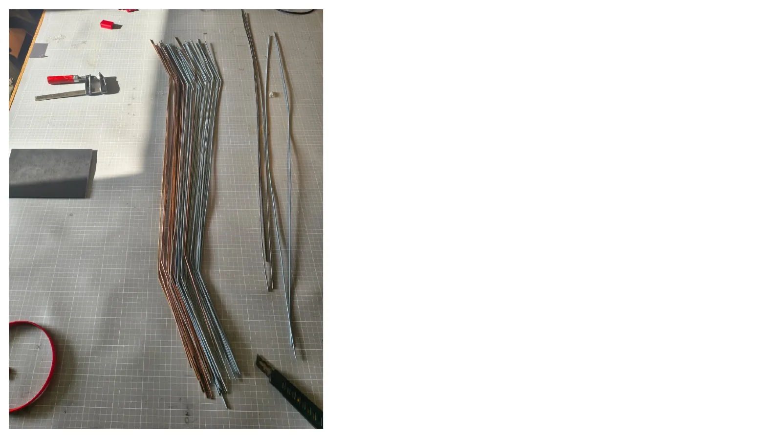
The arm travels in 3D and rotates to follow the set path planes: first in the XY plane, then rotating in the XZ plane perpendicular to the rod, then moving in Y until it can grip the rod ready to bend. - 05 — Bend at 120 degrees
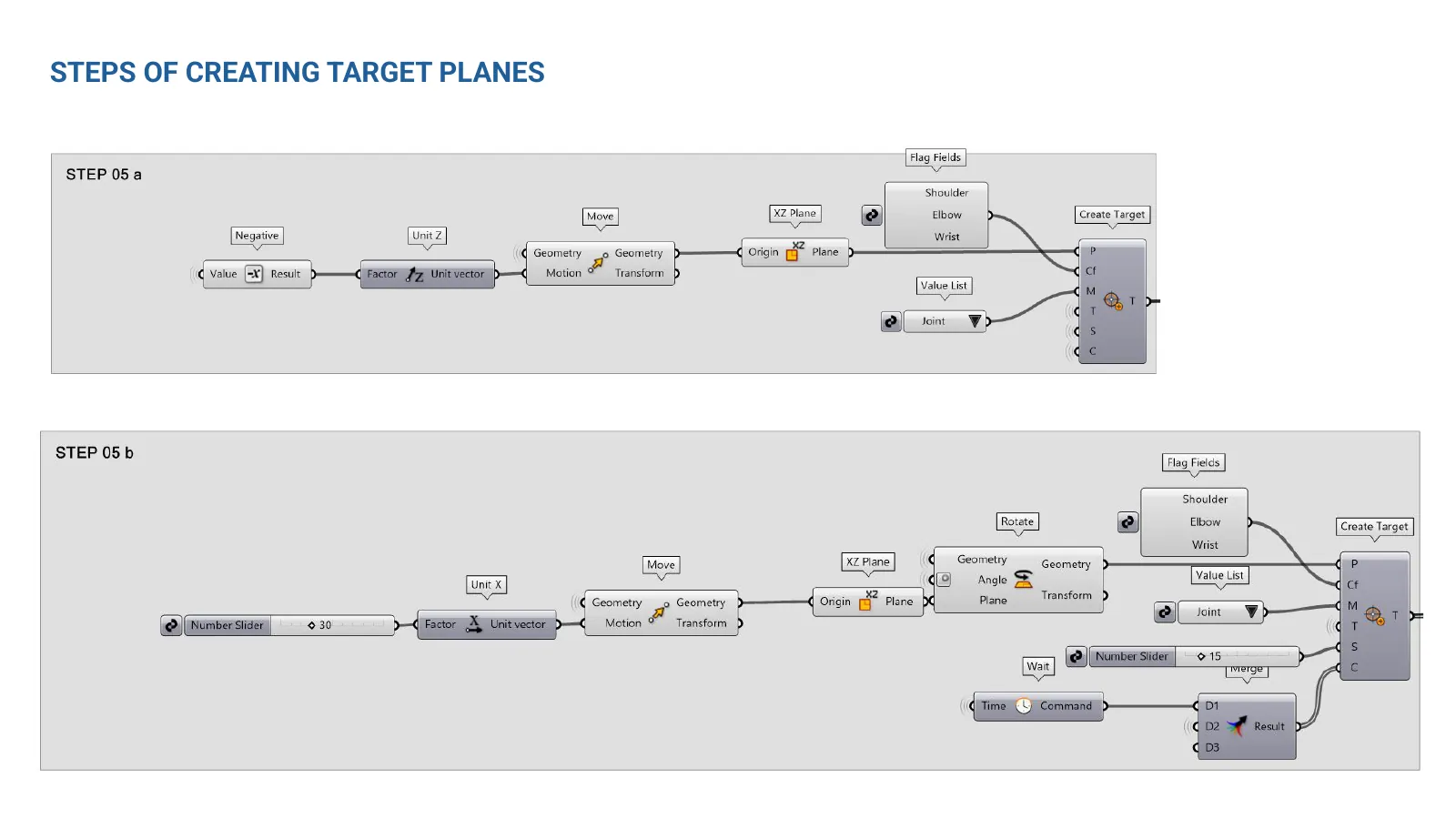
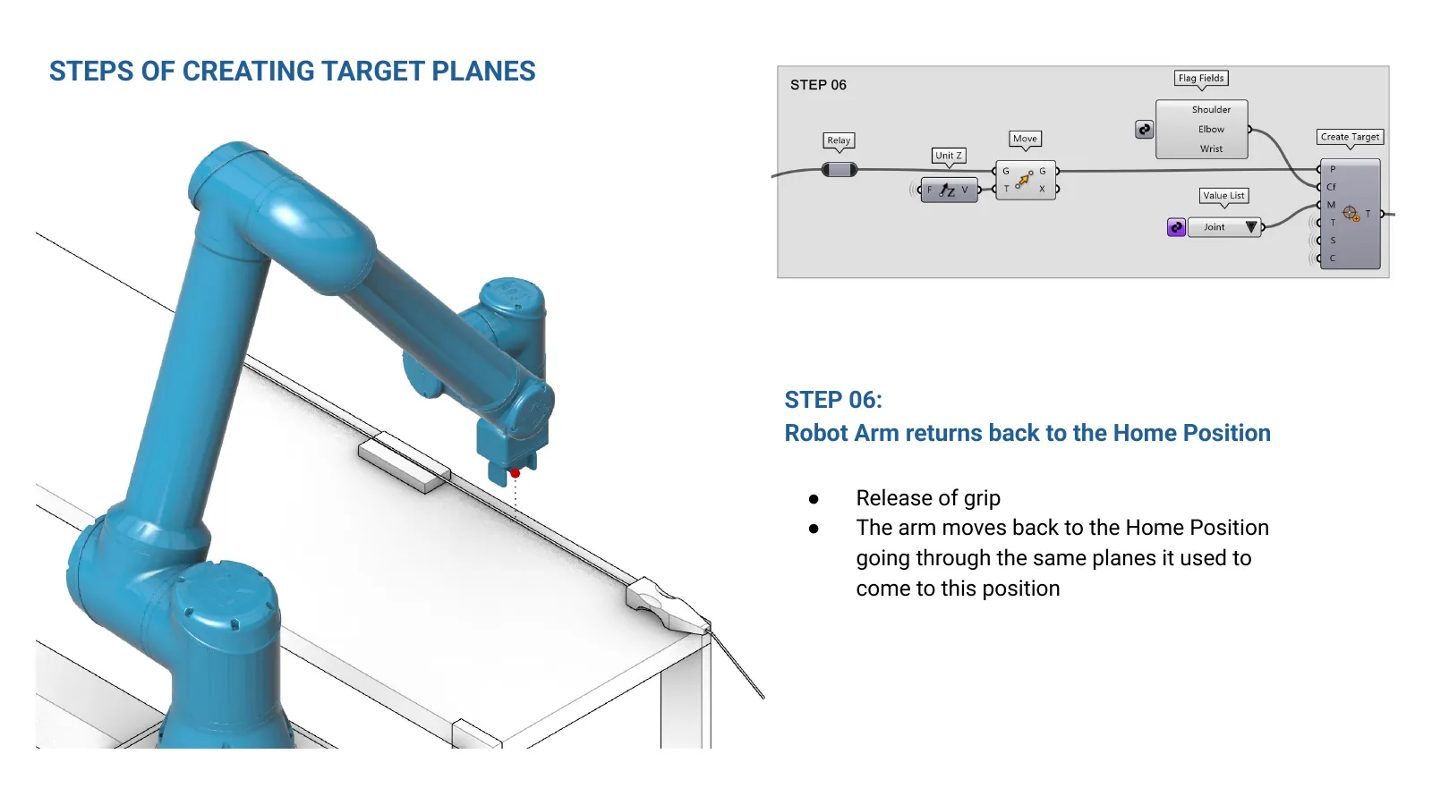
The gripped rod is bent down through 30 degrees, the arm waits, the grip releases, and it returns to the ready-to-bend position. - 06 — Back to the home position
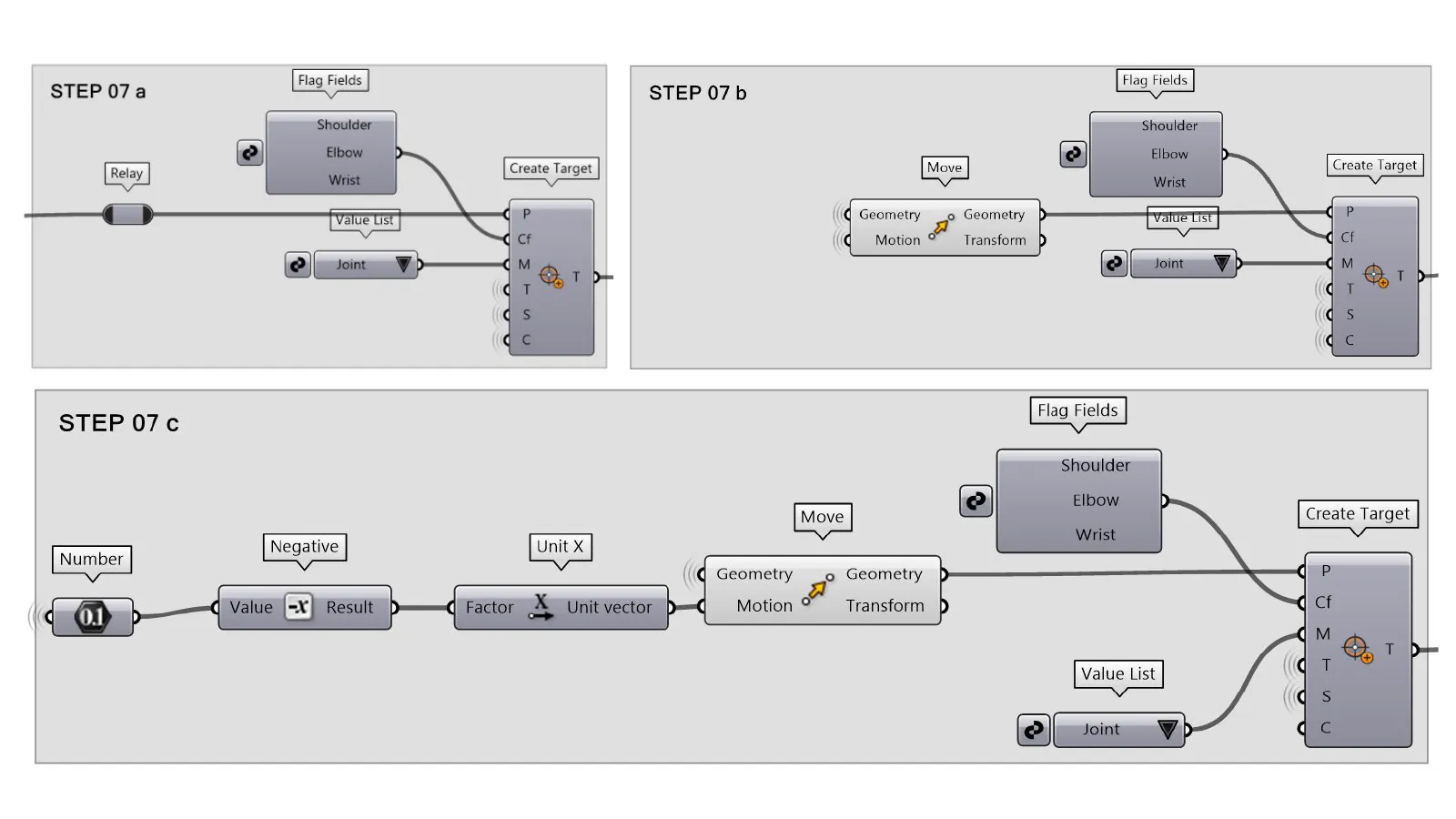
The grip releases and the arm retraces the same planes back to where the cycle started. - 07 — Three linear moves through the tool
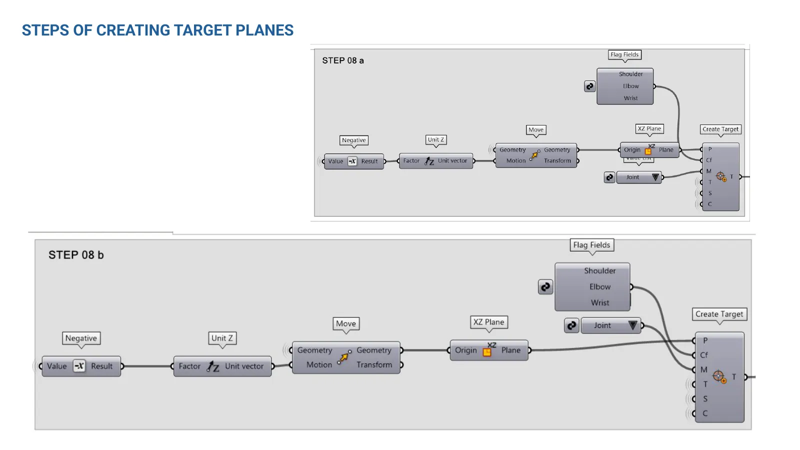
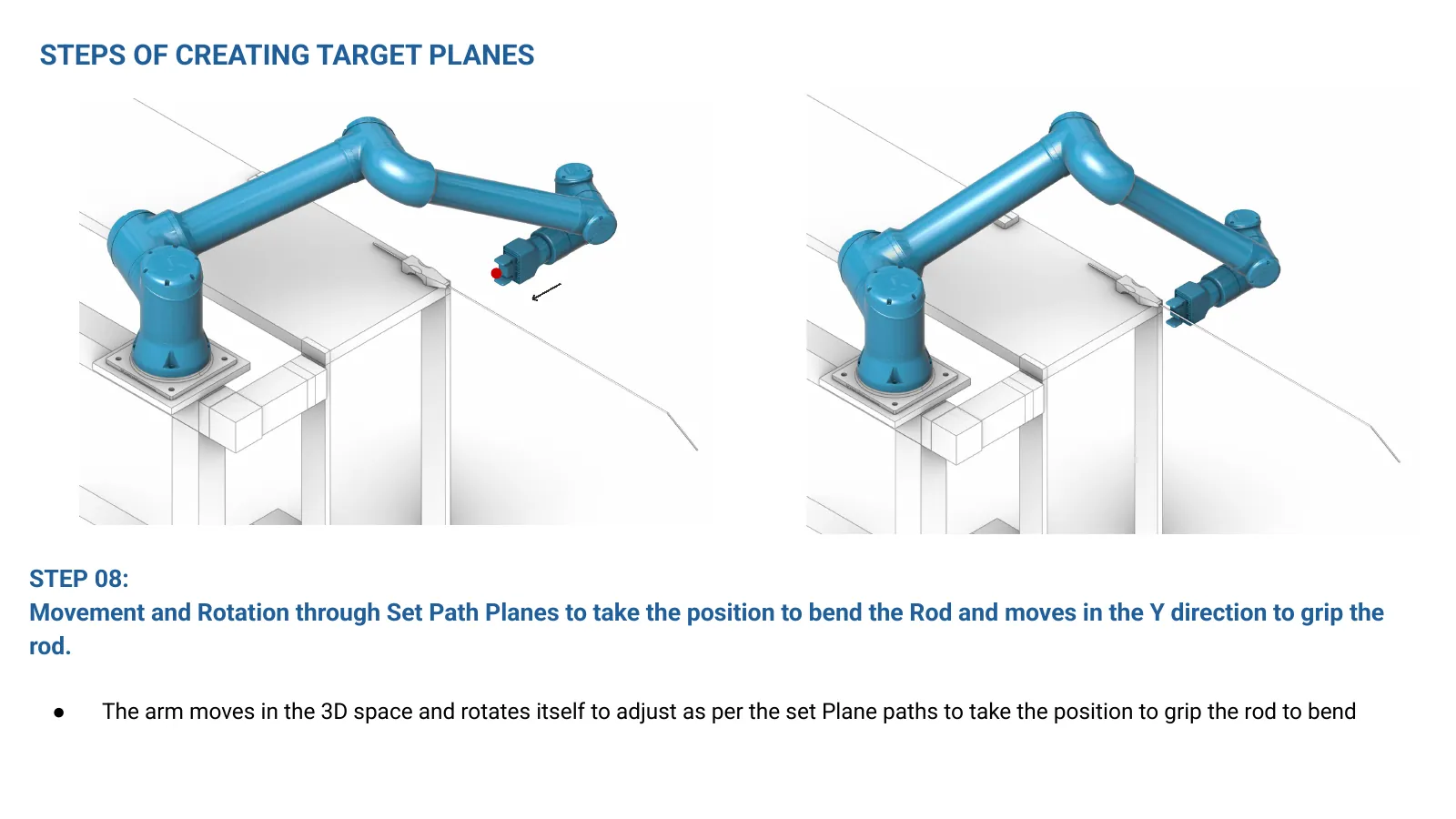
As in step 03, but the feed through the tool repeats three times in one loop. - 08 — Move and rotate for the second bend
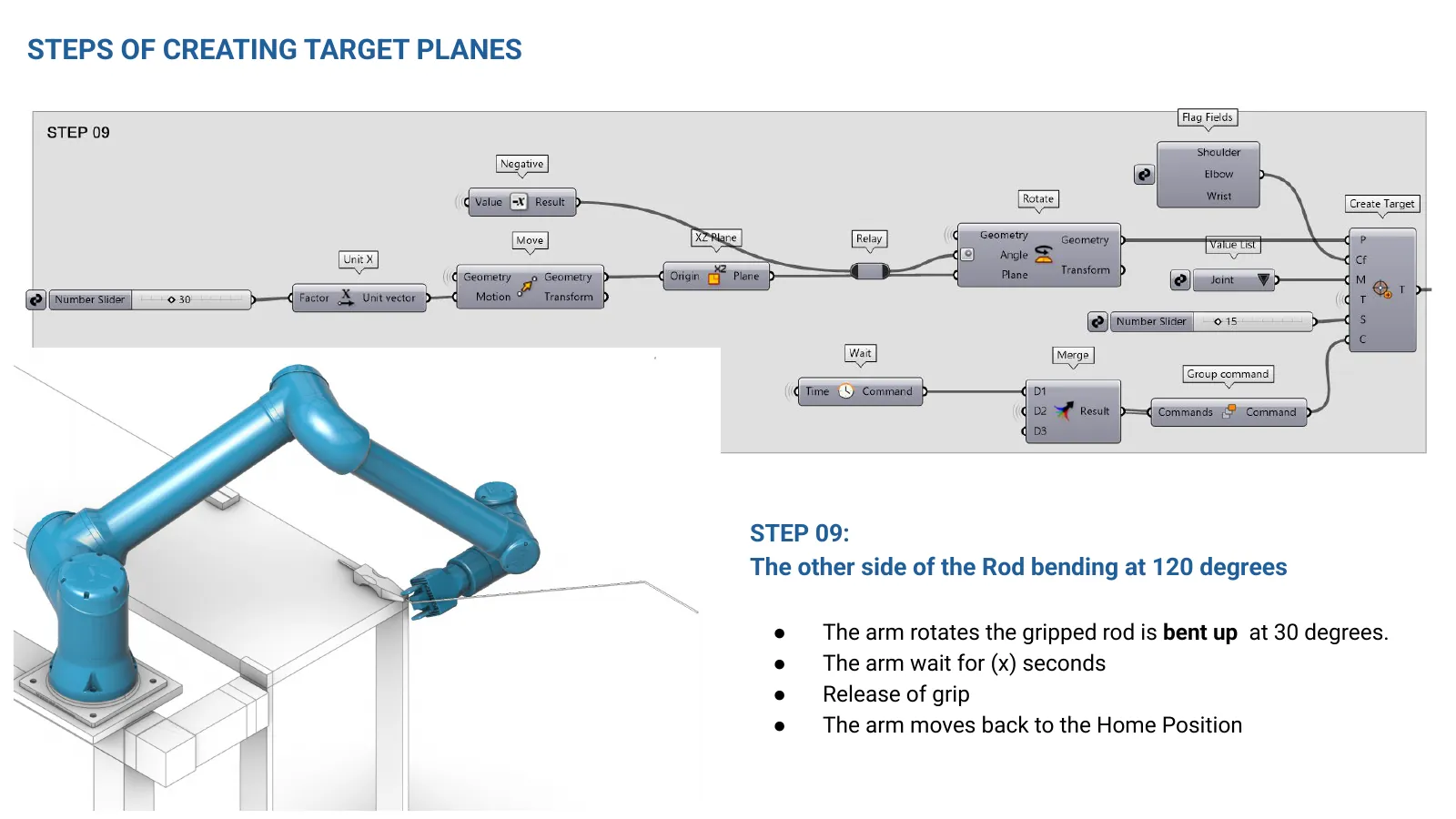
The arm repositions through the path planes and moves in Y to grip the rod again. - 09 — The other side, bent at 120 degrees
The rod is bent up through 30 degrees, the arm waits, releases, and returns home.
Watch it run
The same cycle, simulated in Grasshopper before it was sent to the arm.
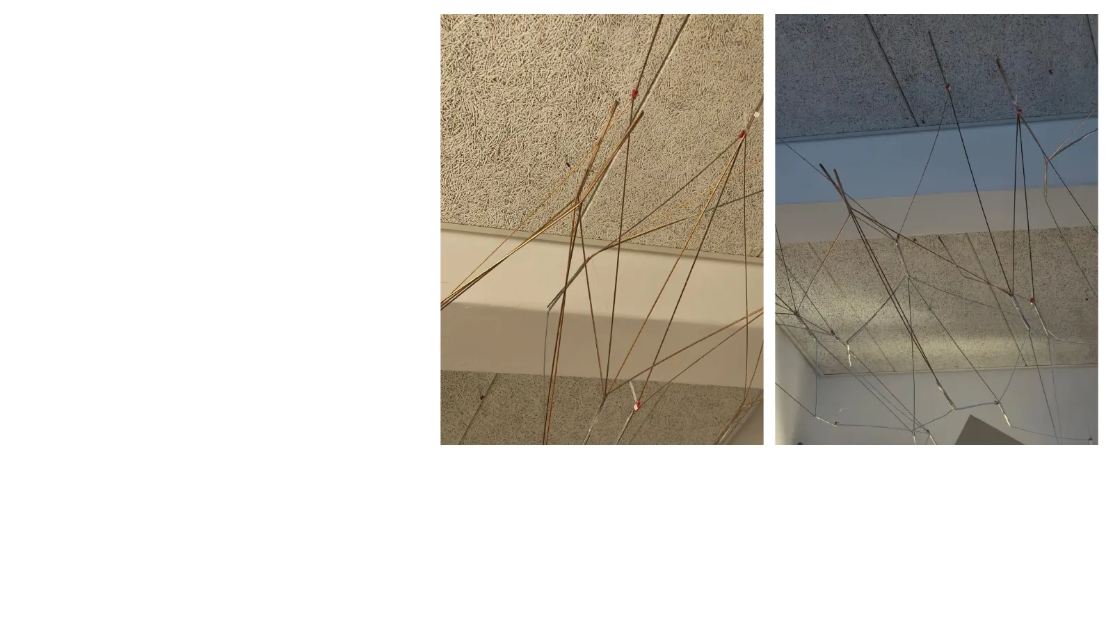
From the week
Making, breaking, re-printing and hanging — most of the work was not the robot.
The full deck
All 57 slides of the presentation, in order.